
How an Engineered Vinyl Seawall Goes From Site Assessment to Final Inspection
The vinyl face matters, but so do embedment, anchoring, drainage, backfill, installation quality and component connections. Compare complete proposals.
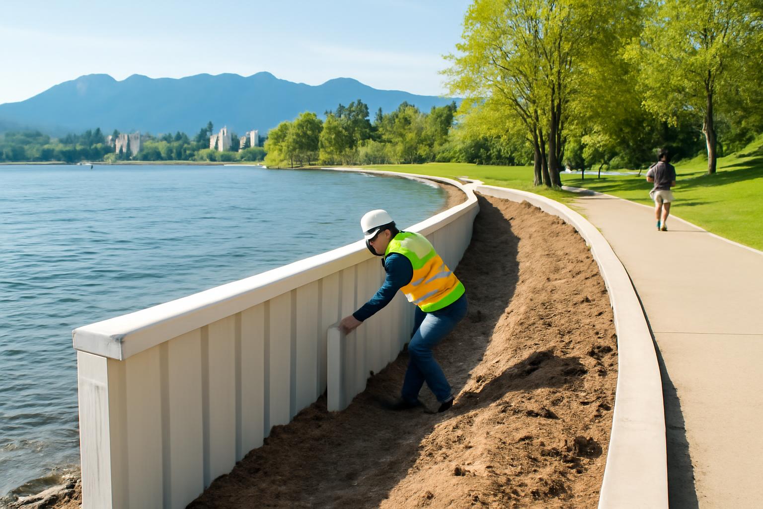
Vinyl seawall construction is sometimes reduced to a simple description: interlock PVC panels, drive them along the shoreline, add a cap, and backfill. That summary leaves out much of what determines whether the completed wall performs as intended.
A seawall is a soil-retention system that interacts with soil, groundwater, surface water, waves, nearby structures, and loads behind the wall. The vinyl face matters, but so do pile embedment, anchoring, drainage, backfill, installation quality, and the connections between components.
This article provides a general, non-prescriptive overview for property owners, developers, HOA representatives, and project planners comparing systems and contractor proposals. It is based largely on commercial guidance from manufacturers, suppliers, and marine contractors—not independent engineering standards or jurisdiction-specific regulations. It cannot replace a site investigation, sealed engineering documents, manufacturer requirements, permits, or qualified marine construction.
What a Vinyl Seawall Is—and What It Actually Has to Do
A conventional vinyl seawall generally consists of interlocking polyvinyl chloride, or PVC, sheet piles installed along a shoreline. The sheets form a continuous retaining face intended to hold soil and reduce shoreline erosion. Part of each sheet remains exposed, while another portion is embedded below the mudline or ground surface.
The panels are only one part of the structure. Depending on the engineered design, the complete wall may include:
- Embedded vinyl sheet piling
- Horizontal walers
- Tie rods
- Buried deadmen or another anchoring arrangement
- Drainage and filter materials
- Selected backfill
- A wood, concrete, vinyl, composite, or hybrid cap
- Site-specific toe or scour measures
- End returns or transitions
- Fasteners, connectors, reinforcement, and related hardware
The wall face receives pressure from retained soil and water behind it. Waves, wakes, water-level changes, boat traffic, and other shoreline conditions may also affect the system. Buildings, vehicles, landscaping, stored materials, or other loads behind the wall can influence the project design.
Replacing one material without correcting poor anchoring, unstable soil, inadequate drainage, or lost backfill may leave the underlying problem unresolved.
PVC does not undergo the electrochemical corrosion associated with steel. That distinction applies to the vinyl itself, not necessarily to the entire seawall. Tie rods, fasteners, plates, reinforcement, and other metallic components may still deteriorate. Commercial comparison guidance similarly describes vinyl performance as dependent on anchoring, stable backfill, soil conditions, and drainage—not corrosion resistance alone (Seawall Savers’ material comparison).
Interlocks should not be treated as proof that a wall is completely watertight. Because water trapped behind a wall can increase pressure, the design may intentionally provide controlled drainage while using filters to limit the loss of fine soil.
Material terminology also matters:
- Conventional vinyl sheet piling uses interlocking PVC sheets as the retaining face.
- Reinforced vinyl supplements a vinyl wall with stronger profiles, reinforcement, or another structural arrangement.
- Composite piling uses fiber-reinforced polymer or another composite material. Its stiffness, strength, and connections should not be assumed to match PVC.
- Concrete-filled vinyl forms use proprietary vinyl components as permanent forms for reinforcing steel and cast-in-place concrete.
The last category is materially different from a conventional hollow vinyl wall. One manufacturer, for example, describes an eight-inch steel-reinforced concrete wall cast inside dual-interlocking vinyl forms (Truline’s hybrid wall description).
Preconstruction: Site Investigation, Engineering, Permits, and Access
A credible project starts with the shoreline rather than a product catalogue. Before a profile or installation method is selected, the project team should establish what is being retained, what conditions act on the wall, and what access is available.
A preliminary assessment commonly considers:
- The proposed alignment and property boundaries
- Existing and proposed grades
- Visible wall height and water levels
- Erosion, settlement, voids, seepage, or lost backfill
- Existing walls, revetments, docks, lifts, and outfalls
- Known utilities and nearby structures
- Wave, wake, current, storm, and boat-traffic exposure
- Land-side and water-side access
- Staging and material-storage constraints
- Conditions at each end of the proposed wall
- Whether an old wall will remain or be removed
If an existing wall is present, its condition may affect both design and construction.
Why soil and groundwater investigation comes first
Sheet length cannot be selected from exposed wall height alone. The designer must understand the material through which the sheets will be installed and the soil expected to provide below-grade resistance.
Possible conditions include sand, clay, soft sediment, organic soil, fill, dense layers, cobbles, buried debris, or shallow rock. Groundwater also matters because water behind the wall can add pressure and transport fine soil through available openings.
The appropriate investigation is project-specific. It should be defined by the responsible professionals rather than copied from a generic checklist. A proprietary wall manufacturer expressly recommends obtaining a soil report before selecting component lengths and installation requirements (Truline’s installation overview).
Design inputs commonly include:
- Soil conditions and stability
- Groundwater and drainage conditions
- Expected water levels
- Wave, wake, storm, and current exposure
- Wall geometry and retained height
- Loads behind the wall
- Potential vessel, debris, or other impacts
- Nearby docks, foundations, buildings, and utilities
- Available anchoring area
- Land-side and water-side access
- Product-specific design values and installation limits
From those inputs, the responsible engineer determines the panel profile, sheet length, toe elevation, allowable exposed height, anchoring arrangement, drainage concept, backfill requirements, cap details, transitions, and any required reinforcement.
Generic dimensions found online are not safe substitutes. A depth, spacing, or exposed-height limit published for one profile may apply only to that manufacturer’s product and assumed conditions. Even adjoining properties can require different solutions because their grades, fill, structures, water depth, or shoreline geometry differ.
Permits and environmental review
Permitting requirements vary by location. Commercial installation guidance notes that approvals may involve local authorities, state agencies, and, for some United States projects, the U.S. Army Corps of Engineers (Everlast’s permitting overview).
That broad observation does not establish the requirements for any particular property. It also does not provide Vancouver, British Columbia, Canadian, or other jurisdiction-specific guidance.
Before ordering materials, an owner should ask the authorities governing the site:
- Which property, shoreline, waterward, or jurisdictional boundaries must be established?
- Which local, regional, state, provincial, or federal approvals may apply?
- What surveys, engineering documents, environmental information, or application materials are required?
- Are there limits on alignment, wall height, waterward encroachment, installation methods, or construction timing?
- What inspection, documentation, or completion requirements apply?
- Who is responsible for applications, fees, revisions, and final closeout?
These are questions to confirm directly with the relevant authorities and project professionals, not a universal legal procedure.
Access can change the project
Construction logistics can affect system selection, equipment, staging, and cost. The project team should establish whether materials and machinery can reach the alignment from land, water, or both.
Questions include:
- Is there room for the proposed installation equipment?
- Can sheets be moved around buildings, fences, trees, or other obstructions?
- Would water-side installation or a temporary working platform be needed?
- Is there space for the proposed anchoring arrangement?
- Where will demolition debris and new materials be handled?
- Must docks, decks, fences, or landscaping be temporarily removed?
- How will the contractor protect surrounding property and restore disturbed areas?
Restricted access may favor lighter components, but it does not guarantee simple, inexpensive, or equipment-free construction. Additional handling, smaller machinery, water-side work, or a different wall arrangement may be necessary.
The Main Components of an Anchored Vinyl Seawall
Understanding the hidden components makes it easier to compare drawings and proposals.
Interlocking sheet piles and embedment
Interlocking sheets create the wall face.
The required depth depends on the selected profile, soil, retained height, water conditions, anchoring, and other project demands. It is not a universal percentage of the visible wall.
Drive guide
A drive guide helps keep sheets aligned during the sheet-driving process How to Build and Install a Seawall – Everlast Synthetic Products. It physically supports the sheets as they are placed and installed, helping the crew maintain the intended alignment and vertical position.
A string line can identify the general wall line, but commercial installation guidance distinguishes it from a rigid guide capable of restraining the panels. The first sheets are particularly important because later sheets tend to follow their alignment.
Walers
Walers are horizontal members positioned along the wall.
Their material and configuration vary by system. A waler may be timber, steel, concrete, composite, or another material specified by the design.
Tie rods, deadmen, and other anchors
A typical anchored vinyl wall uses tie rods extending from the wall or waler to deadmen buried behind it.
Deadmen may take different forms depending on the design. Not every wall uses conventional tie rods and buried deadmen; some systems use another engineered arrangement, while some walls may rely more heavily on pile stiffness and embedment.
Whether a wall can act without conventional anchors cannot be decided from generic guidance. The drawings should identify the anchoring concept, locations, elevations, connections, materials, and installation requirements.
Drainage and filters
Drainage features provide controlled paths for water behind the wall. Depending on the design, the system may use drainage aggregate, filter material, pipes, outlets, weep holes, or surface-water controls.
There is no universal outlet type or spacing appropriate for every soil and wall system.
Backfill
Backfill is part of the retaining system, not merely material used to fill an excavation.
The proposal and drawings should identify whether existing soil can be reused or imported material is required. They should also define responsibility for placement, verification, and any testing required by the project documents.
Top cap
Cap materials and dimensions vary. A decorative cover should not be assumed to provide the same function as a reinforced structural cap.
The project drawings should include a labeled cross-section. The following conceptual figure shows the relationships that should be visible; it is not a design detail and is not to scale.
flowchart LR
    W["Water"] --- F["Exposed vinyl<br/>sheet-pile face"]
    F --- E["Embedded sheet piling<br/>below mudline"]
    F --- C["Top cap"]
    F --- WA["Waler"]
    WA --- T["Tie rod"]
    T --- D["Buried deadman<br/>or engineered anchor"]
    F --- DR["Drainage zone<br/>and filter material"]
    DR --- B["Compacted design backfill"]
    E --- S["Site-specific toe<br/>or scour measures"]
A project-specific drawing may also need to show water levels, finished grade, mudline, wall and toe elevations, drainage outlets, wall ends, adjoining structures, and transitions.
Vinyl Seawall Construction Step by Step
The following sequence is an owner-level overview, not an installation manual. Actual sequencing and acceptance criteria must come from the approved design, manufacturer instructions, permits, and contractor’s project plan.
1. Prepare and control the site
The contractor establishes access, staging, alignment references, and the permitted work area. Required demolition or selective removal is coordinated with the new wall alignment and construction sequence.
At this stage, the owner should confirm:
- The approved drawings are available on site.
- The proposed alignment matches the permitted project.
- Delivered materials match the named product and profile.
- Responsibilities for access, demolition, protection, and restoration are clear.
- Required project controls and inspections have been assigned.
2. Establish line and elevation
The proposed wall line and relevant elevations are transferred to the site. Corners, curves, wall ends, and transitions should correspond to the project drawings.
A rigid drive guide is then installed to support the panels. Commercial manufacturer guidance identifies the guide—and straight, plumb starter sheets—as central to keeping the wall aligned.
Owner review point: Ask how the contractor will verify the wall line, top elevation, curves, and transitions as installation progresses.
3. Set the starter sheets
The first sheets establish the geometry of the run. If they lean, rotate, or drift, later sheets may follow the same error. Poor initial alignment can also make interlocks harder to engage and affect the finished cap line.
The installation team therefore checks the starter sheets against the guide and project controls before continuing.
Owner review point: Confirm that the project’s inspection or documentation plan addresses starter-sheet alignment and visible panel condition.
4. Continue the interlocking run
Depending on the product and approved installation plan, sheets may be threaded together before driving, added individually, or advanced in pairs. The method depends on the profile, soil, equipment, and manufacturer requirements.
During installation, the contractor should follow the project’s criteria for:
- Wall line and elevation
- Vertical alignment
- Interlock engagement
- Visible panel damage
- Required sheet length and toe elevation
- Unexpected obstructions or refusal
Generic field improvisation should not replace the approved response to an obstruction, damaged panel, or sheet that does not reach its design position. The proposal should state who has authority to evaluate changed conditions and approve a revised detail.
5. Install walers and anchoring
Walers, tie rods, deadmen, or other anchors are installed according to the engineered layout. Their spacing, elevations, connections, and materials should not be taken from a generic online example.
Before these components are concealed, the owner should ask who will confirm:
- Anchor type and location
- Waler and connection details
- Materials and specified protection
- Any required project inspection or testing
- Approved changes from the drawings
These questions help establish a clear record without substituting the owner’s judgment for professional inspection.
6. Complete drainage and soil-retention details
Drainage zones, filters, pipes, outlets, or weep holes are installed at the stage shown in the project documents. These components should be coordinated with anchors, interlocks, old structures, and wall ends.
A complete proposal should explain both sides of the drainage problem: how water will be relieved and how fine soil will be retained.
Owner review point: Request documentation of concealed drainage and filter components if the drawings, permit, or inspection plan requires it.
7. Place backfill in controlled stages
Backfill should be the material specified for the project rather than automatically reused excavation. Placement and any required verification should follow the drawings and specifications.
The central distinction for an owner is that backfilling is a controlled construction operation—not simply pushing available soil behind the completed panels. The contractor should explain how the work will protect the drainage system, anchors, and wall alignment.
8. Construct the cap and complete transitions
The cap is installed after the wall, anchoring, drainage, and backfill have reached the stage required by the design. Its connections, reinforcement, joints, and finish depend on the selected system.
Wall ends and transitions require particular attention because the retaining system must connect appropriately to adjoining walls, returns, structures, or natural shoreline.
Owner review point: Confirm that the completed cap, drainage openings, wall ends, and adjoining work match the approved details.
9. Restore, inspect, and document
After construction, disturbed areas are restored in accordance with the project scope. Final review may address wall line, elevation, visible panel condition, cap condition, drainage features, transitions, and approved field changes.
The closeout package may include, where required by the contract or authorities:
- Approved drawings and permits
- Product information
- Inspection or survey records
- Photographs of concealed and completed work
- Approved field changes
- Available as-built information
- Warranty documents
- Maintenance instructions
Baseline photographs and records give the owner a reference for recognizing later movement or deterioration.
Manufacturer installation material describes this work only as a general overview and directs readers to project-specific support. It should not be treated as a do-it-yourself operating guide. Installation should be performed by appropriately qualified contractors under the professional oversight and approvals required for the project.
How Soil and Access Affect the Installation Method
There is no universal soil-to-equipment formula for vinyl piling. Method selection depends on the soil, required sheet length, panel profile, obstructions, access, product requirements, and restrictions established for the project.
Commercial sources describe several possible approaches:
| Method | General use described in commercial guidance | Important limitations to resolve | Access questions |
|---|---|---|---|
| Vibratory driving | Advancing piling in some granular or loose soils | Product compatibility, obstructions, surrounding conditions, required penetration | Can the carrier and lifting equipment reach and operate at the wall? |
| Backhoe-mounted plate compaction | Installing sheets in moderate or softer soil | Controlled loading, panel-head protection, alignment, effectiveness in denser material | Is suitable excavator access available? |
| Direct compression | Pressing sheets in very soft soil | Limited effectiveness in stronger layers and product-specific restrictions | Can equipment remain correctly positioned? |
| Hydraulic pile hammer | Impact installation where allowed by the selected product and plan | Product limits, surrounding conditions, support equipment, noise and vibration constraints | Is there room to lift and support the hammer? |
| Jetting | Loosening or removing soil beneath piling | Soil displacement, environmental restrictions, discharge control, effect on assumed soil support | Are pumps, water supply, hoses, and permitted controls available? |
| Guided mandrel | Supporting selected profiles through harder soil or over longer lengths | Specialized, product-specific equipment | Is there room to place and extract the mandrel? |
| Pretrenching | Creating a trench where direct installation is unsuitable | Temporary ground conditions, excavation handling, replacement material | Is excavation and spoil-handling access available? |
A commercial supplier describes vibration, plate compaction, direct compression, and hydraulic impact as possible methods while emphasizing that equipment selection varies with soil and piling characteristics (Building Products Plus installation methods).
These descriptions do not establish operating parameters or prove that a method is suitable for a particular site. Hard layers, buried obstructions, long sheets, or shallow rock may require more investigation, a different installation method, removal of an obstruction, or redesign.
Jetting deserves particular scrutiny because it intentionally loosens or removes soil. The contractor should identify whether it is permitted, how displaced material will be handled, and how the method remains consistent with the engineered design. Product-specific installation guidance cannot establish environmental or legal approval for an individual property.
It is also inaccurate to say that vinyl construction never requires heavy equipment. Lightweight sheets may be easier to transport than concrete elements, but installation can still involve excavators, driving equipment, pumps, lifting machinery, barges, or other substantial resources.
At restricted-access properties, lighter components may widen the range of feasible approaches. Sheets might be brought through a narrow yard or installed from the water. Neither option guarantees a shorter schedule or lower cost. A proposal should name the intended equipment and explain how it will reach the wall, install the specified sheets, and leave the property.
Where Conventional Vinyl Fits—and When Another System May Be Better
Material selection should follow the shoreline’s structural and environmental conditions rather than a marketing preference.
Conventional vinyl is commonly presented for residential properties, sheltered canals, inland waters, restricted-access locations, and moderate-exposure applications. Those categories do not establish suitability by themselves. Retained height, soil, groundwater, anchoring, impacts, nearby structures, and other project demands still govern the design.
A central limitation is relative stiffness. Commercial comparison guidance describes conventional vinyl as less stiff than many concrete or steel systems and more dependent on anchoring and stable soil. Higher retained grades, weak soil, significant impacts, or more demanding exposure may require a stronger profile, reinforcement, a hybrid system, or another wall type.
| System | General characteristics | Conditions that may support consideration | Issues to evaluate |
|---|---|---|---|
| Conventional vinyl | Interlocking PVC sheets; corrosion-resistant wall face; relatively light components | Residential, sheltered, moderate-exposure, or restricted-access projects | Stiffness, deflection, embedment, anchors, drainage, impacts |
| Reinforced vinyl | Vinyl supplemented by reinforcement or a stronger arrangement | Demands beyond a basic profile where the proprietary system remains suitable | Reinforcement, connections, installation, inspection |
| Composite piling | Fiber-reinforced or other composite sheet piling | Projects needing different synthetic-pile strength or stiffness | Product-specific properties, connections, damage tolerance |
| Concrete-filled vinyl forms | Reinforced concrete placed within permanent proprietary vinyl forms | Projects seeking a concrete structural element within a vinyl form | Reinforcement, concrete placement, proprietary design, access |
| Concrete | Precast or cast-in-place structural wall | Higher stiffness or structural demand, subject to design | Weight, access, cracking, reinforcement, foundations, repairs |
| Steel | High-strength driven piling | Heavy structural demand, long piling, or impact considerations | Corrosion protection, coatings, maintenance, driving conditions |
Concrete or steel may be considered where strength, stiffness, pile length, or impact resistance dominates. Those systems have their own design, corrosion, cracking, coating, access, and maintenance considerations. No material is automatically best.
Commercial contractor guidance likewise presents vinyl and composite panels as possible options for smaller walls, reinforcement, and restricted-access sites while noting that concrete generally provides greater structural strength and that high-impact shorelines may call for another material (Duncan Seawall’s material-selection overview).
Three bounded examples illustrate the decision:
Sheltered residential canal with restricted access. Conventional anchored vinyl may be practical where exposure and impacts are modest and the soil can support the designed piling and anchors. Lighter panels may help with transport, but installation equipment and anchor access still require planning.
Sandy or weak-soil lakefront. Vinyl may remain feasible, but the design could call for different sheet lengths, anchoring, drainage, filters, selected backfill, or toe treatment. A light wall face does not compensate for inadequate soil resistance.
Exposed high-energy shoreline. Strong waves, storm demand, vessel impacts, high retained grades, or heavy loads may make a conventional vinyl profile too flexible. Reinforced vinyl, composite piling, concrete-filled forms, concrete, steel, a hybrid system, or another shoreline treatment may warrant consideration.
Claims that vinyl is universally cheaper, stronger, greener, longer-lasting, maintenance-free, or storm-proof should not replace a project-specific comparison.
Cost, Schedule, Warranties, and Contractor Proposals
The available evidence does not support a universal price per linear foot or a standard construction schedule. A meaningful estimate requires a defined wall, site conditions, access plan, jurisdiction, and scope.
Potential cost categories include:
- Surveying and site assessment
- Geotechnical and engineering work
- Permit preparation and fees
- Mobilization and site access
- Water-side equipment or temporary access
- Demolition or front-wall construction
- Sheet profile, quantity, length, and delivery
- Walers, tie rods, deadmen, and connections
- Drainage and filter materials
- Backfill and any required verification
- Cap construction
- Wall ends, transitions, or toe measures
- Inspection and closeout documentation
- Landscaping, paving, dock, deck, or fence restoration
- Regional labor and contractor overhead
- Allowances for concealed conditions
Commercial guidance identifies wall size, location, material grade, soil, added features, and installation complexity as cost drivers (Decks & Docks’ vinyl seawall guide). The exact inclusions and terminology will vary by contractor and jurisdiction.
Two walls of the same length can therefore have substantially different prices. A low, straight wall with easy land access is not directly comparable with a taller curved wall requiring long sheets, extensive anchoring, demolition, water-side installation, and restoration around existing structures.
Schedule also depends on project-specific factors. Rather than accepting a generic duration, ask each bidder to identify assumed approval timing, material availability, mobilization, required inspections, dependencies, and changed-condition allowances.
Initial price should be separated from lifecycle risk. Vinyl’s corrosion resistance at the wall face does not guarantee the lowest total ownership cost. Drainage problems, soil loss, anchor deterioration, cap damage, impacts, or premature replacement can alter the long-term result.
Proposal-comparison checklist
Require each bidder to identify:
- Wall alignment, length, elevations, and retained height
- Named manufacturer, product, and profile
- Sheet lengths and design toe elevations
- Responsibility for engineering and revisions
- Assumed soil and groundwater conditions
- Installation method and equipment
- Procedure for obstructions, refusal, or damaged panels
- Waler, tie-rod, deadman, or alternative anchor scope
- Drainage and filter scope
- Backfill source and placement requirements
- Cap material and intended function
- Wall ends, transitions, and any toe measures
- Demolition and disposal responsibilities
- Permit preparation and compliance responsibilities
- Inspection and closeout responsibilities
- Restoration work
- Exclusions and owner-supplied items
- Allowances, unit prices, and change-order triggers
- Material and workmanship warranty documents
A low bid may omit engineering, anchors, drainage, imported backfill, restoration, or water-side equipment included elsewhere. Compare complete systems and scopes rather than bottom-line totals.
Three different time concepts
Material warranty refers to the manufacturer’s written coverage for the product, subject to its terms and exclusions.
Workmanship warranty refers to the installer’s written obligations for covered construction work.
Engineered design life is a project-specific design objective based on stated assumptions and performance criteria.
None is the same as observed field service life. Commercial sources publish multidecade estimates for vinyl, but those estimates are conditional and do not establish how a particular wall will perform. Contractor guidance also notes that limited material warranties may exclude conditions such as storm damage, installation defects, and normal wear (Property Image’s warranty discussion).
Owners should read the actual product warranty and construction contract rather than relying on a lifespan statement in a proposal. Question bids containing universal embedment depths, vague anchoring, omitted drainage, unqualified service-life promises, or claims that permits and engineering are unnecessary.
Repair, Retrofit, Inspection, and Warning Signs
Some deteriorated walls can be repaired or reinforced rather than completely removed. In selected projects, a new vinyl, composite, or concrete-filled vinyl wall may be installed in front of an older wall.
A front-wall installation can reduce demolition, but feasibility depends on:
- Stability of the existing wall during construction
- Space for the new alignment and piling
- Available anchoring area
- Drainage continuity
- Hidden foundations, debris, or old anchors
- Property and jurisdictional boundaries
- Loss of waterfront area
- Connections to docks and adjoining walls
- Equipment access
- Permit conditions
The existing structure may also obstruct installation or conceal deterioration.
The broader professional evaluation may consider monitoring, repairing drainage, stabilizing soil, repairing anchors or a cap, reinforcing the wall, installing a new front wall, raising the structure, or replacing it. The appropriate option depends on the condition and intended function of the existing wall.
Observable warning signs include:
- New or increasing bowing
- Leaning or rotation
- Settlement behind the wall
- Cracked, displaced, or deteriorated caps
- Open or damaged interlocks
- Exposed, loose, bent, or corroded anchors
- Depressions or voids behind the wall
- Loss of backfill
- Seepage carrying soil
- Blocked or changed drainage outlets
- Exposed sheet toes
- Erosion around wall ends
- Abrupt changes after storms or impacts
Corrosion-resistant PVC does not eliminate the need to examine metallic anchors, fasteners, caps, drains, backfill, adjoining shoreline, and nearby structures.
After construction, preserve baseline photographs, wall-alignment observations, drainage locations, product data, permits, approved drawings, inspection records, warranty documents, and available as-built information. Follow the maintenance instructions prepared for the project rather than assuming a universal inspection interval.
Prompt professional assessment is appropriate when an owner observes new bowing, rapid soil loss, an exposed void, anchor distress, a displaced cap, progressive settlement, or a sudden drainage change.
Frequently Asked Questions
How deep must vinyl sheet piling be driven for a seawall?
There is no universal embedment depth. Required sheet length and toe elevation depend on the soil, retained height, groundwater, water conditions, profile, wall stiffness, anchors, loads, and other project demands.
The engineered drawings should state the required sheet and toe information. A proposal should also explain how unexpected obstructions or incomplete penetration will be evaluated rather than relying on a generic minimum.
Can a vinyl seawall be installed without heavy equipment?
Lightweight components may be easier to transport through a restricted property, but that does not make vinyl seawall construction equipment-free.
Depending on the soil, profile, sheet length, access, and selected system, the work may involve an excavator, driving equipment, pumps, lifting machinery, compaction equipment, or water-side equipment. The proposal should identify the intended machinery and access plan.
How much does vinyl seawall construction cost per linear foot?
The supplied evidence does not support a reliable universal per-linear-foot figure. Cost varies with wall height, sheet profile and length, soil, anchoring, drainage, cap, demolition, alignment, access, permits, engineering, marine equipment, restoration, and regional labor.
Ask for an itemized proposal based on defined dimensions and assumptions. Confirm what is included before comparing unit prices.
Can vinyl sheet piling be installed in front of a failing seawall?
In some cases, yes. Manufacturers and contractors describe front-wall construction as an available option for selected vinyl, composite, and concrete-filled vinyl projects.
Feasibility depends on the old wall’s stability, hidden obstructions, available space, drainage, boundaries, permits, anchors, and access. A qualified professional should determine whether the old structure can remain and how soil loss, voids, and load transfer will be addressed.
How long does a vinyl seawall last, and what does its warranty cover?
A fixed service life cannot be promised from the wall-face material alone. Published multidecade estimates are commercial projections conditioned on product formulation, engineering, exposure, installation, drainage, anchoring, impacts, maintenance, and site stability.
Warranty coverage is narrower than expected service life. Material, workmanship, and design obligations may come from different parties and documents. Read the applicable warranty and contract terms, including exclusions, before signing.
Project-readiness checklist
- [ ] Confirm shoreline, survey, easement, and property-boundary information.
- [ ] Document existing erosion, structures, utilities, grades, and water conditions.
- [ ] Obtain appropriate soil and engineering input.
- [ ] Identify the authorities governing the site and confirm their requirements directly.
- [ ] Define exposure, retained height, loads, impacts, and nearby structures.
- [ ] Compare complete wall systems rather than panel materials alone.
- [ ] Require explicit piling, anchoring, drainage, filter, backfill, cap, and transition details.
- [ ] Verify land-side and water-side access and the proposed installation equipment.
- [ ] Compare bids using the same dimensions, assumptions, inclusions, and exclusions.
- [ ] Separate material warranties, workmanship warranties, and design-life assumptions.
- [ ] Define responsibility for inspections, approved changes, and closeout records.
- [ ] Preserve permits, photographs, product records, warranties, and as-built information.
Vinyl can be a practical seawall material under suitable conditions, but only a site-specific engineered design can establish whether it is appropriate for a particular shoreline.